
Bifurcation lesions, where a main branch (MB) meets a side branch (SB), account for up to 15-20% of all percutaneous coronary interventions (PCI).1 Provisional stenting (PS) has become the default strategy in most bifurcation lesions due to its relative simplicity compared with dedicated two-stent techniques. However, SB occlusion after MB stenting can occur in 6-18% of cases.2 The most common mechanism is plaque or carina shift, which may result in adverse outcomes such as periprocedural myocardial infarction or death.3
While established methods exist to restore SB flow in the event of acute occlusion, these are often time consuming and yield variable success. To mitigate this risk, active SB protection techniques have been developed. The CIT-RESOLVE trial demonstrated that active SB protection reduced the incidence of SB occlusion compared with standard PS (with or without a jailed wire).4 Several of these techniques are summarised in the 17th expert consensus document of the European Bifurcation Club and in the 2020 review by Khan et al.56
From a technical standpoint, active SB protection can be applied in almost all bifurcation lesions, though it is most often employed when the SB diameter is ≥2.0 mm, depending on anatomical and clinical considerations. Anatomical predictors of SB occlusion during PS include ostial SB stenosis >50%, a narrow bifurcation angle (<70°), and baseline SB slow flow (Thrombolysis in Myocardial Infarction [TIMI] <3). Additional intravascular ultrasound (IVUS)- or optical coherence tomography (OCT)-based predictors include significant plaque burden opposite the SB ostium or at the carina, heavy calcification, a carina tip angle <50°, and a short branching point-carina tip length (<1.7 mm) (Central illustration).78
Clinical situations where active SB protection may be particularly valuable include PCI of complex bifurcation lesions in the setting of either ST-segment elevation myocardial infarction (STEMI) or haemodynamic instability, where provisional stenting is favoured but the consequences of SB loss would be especially deleterious. Another unique scenario is in the presence of challenging SB access due to severe angulation, where advanced techniques such as reverse wiring or specialised microcatheters are required. In these cases, active SB protection can preserve SB patency while avoiding the need for difficult rewiring after MB stent implantation.
This review focuses on active SB protection, aiming to clarify nomenclature and outline the practical aspects of the most widely adopted strategies, supported by case examples with intravascular imaging. We also address key concerns, including the risk of equipment entrapment and MB stent deformation.
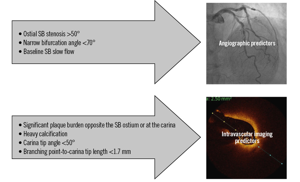
Central illustration. Angiographic and intravascular imaging predictors of SB occlusion during PS. PS: provisional stenting; SB: side branch
Conventional jailed balloon technique
The original jailed balloon technique (JBT) was first described in 2010 by Burzotta et al.9 In this approach, a stent is positioned in the MB, with a long semicompliant (SC) balloon placed from the proximal MB to the SB, with the proximal balloon marker extending beyond the proximal edge of the MB stent. After MB stent deployment, the SB flow is assessed angiographically. If TIMI 3 flow is maintained, the SB balloon is removed, followed by standard post-dilation and proximal optimisation technique (POT). However, if SB flow is compromised, the SB balloon is inflated, resulting in stent distortion in the proximal MB, requiring correction with POT, rewiring, and kissing balloon inflation (KBI). This version of the JBT has become less popular in contemporary practice because of the length of the SB balloon and the potential for extended MB stent deformation.
Case example #1
A 71-year-old male underwent coronary angiography for exertional angina, demonstrating severe stenosis of the proximal left anterior descending artery (LAD) at the bifurcation of a large diagonal branch which was diffusely diseased (Medina 1,1,0) (Figure 1A). IVUS-guided PCI was performed, and after lesion preparation in the LAD, a 3.0×24 mm SYNERGY drug-eluting stent (DES; Boston Scientific) was deployed in the LAD with an uninflated 2.0×30 mm SC balloon jailed in the diagonal branch (Figure 1B). After stent deployment, flow to the SB was lost, accompanied by ST-segment elevation. Reperfusion was achieved by inflating the jailed balloon while protecting the LAD with a 3.5 mm non-compliant (NC) balloon (Figure 1C). IVUS demonstrated minor stent deformation due to the SB balloon rescue inflation (Figure 1D). The SB was rewired using a dual-lumen microcatheter to avoid abluminal wiring, followed by POT of the LAD stent with a 4.0 mm NC balloon. KBI was then performed with a 3.5 mm NC balloon in the LAD and a 2.0 mm SC balloon in the SB. Final angiography and IVUS (Figure 1E, Figure 1F) demonstrated correction of the stent deformation with good stent expansion and preserved flow in both vessels.
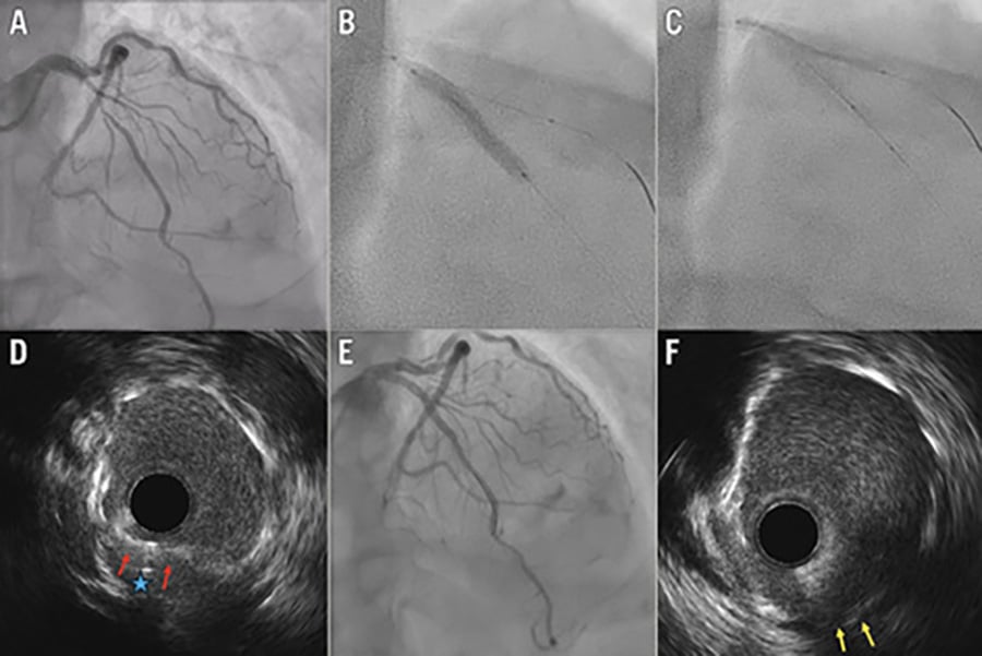
Figure 1. Conventional JBT. A) Baseline angiogram showing severe proximal-to-mid-LAD disease involving a large first diagonal artery. B) LAD stent deployment with an uninflated 2.0×30 mm SC balloon jailed in the diagonal artery, extending beyond the proximal stent edge. C) Rescue inflation due to SB compromise, with a 3.5 mm NC balloon protecting the LAD. D) IVUS showing the jailed diagonal wire (blue star) and minor stent deformation from rescue balloon inflation (red arrows). E) Final angiogram showing good results in both the LAD and diagonal branches. F) Final IVUS showing good stent expansion and correction of deformation after POT (yellow arrows). IVUS: intravascular ultrasound; JBT: jailed balloon technique; LAD: left anterior descending artery; NC: non-compliant; POT: proximal optimisation technique; SB: side branch; SC: semicompliant
Contemporary jailed balloon technique
In the contemporary JBT (C-JBT), the SB balloon is positioned with minimal protrusion into the MB. The SB balloon remains uninflated during MB stent deployment. If TIMI 3 flow is preserved in the SB, the balloon is withdrawn, followed by MB stent post-dilation and POT. If SB flow is compromised, the jailed balloon can be inflated to restore flow, followed by MB stent POT, SB rewiring, and KBI. C-JBT represents a variation of active SB protection designed to minimise MB stent deformation, even if SB rescue is required. Schematic illustrations of JBTs using an uninflated SB balloon are shown in Figure 2.
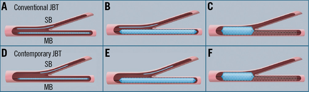
Figure 2. Uninflated JBT techniques. Key steps of the conventional JBT: long SB balloon protrusion (A), which remains uninflated during stent deployment (B), and final POT (C). Key steps of the contemporary JBT: minimal SB balloon protrusion (D), which remains uninflated during stent deployment (E), and final POT (F). JBT: jailed balloon technique; MB: main branch; POT: proximal optimisation technique; SB: side branch
Case example #2
A 64-year-old male underwent coronary angiography for exertional angina, which demonstrated a long segment of calcified disease extending from the proximal to mid-LAD which was positive on fractional flow reserve assessment (Figure 3A). The most severe stenosis was located at the bifurcation (Medina 1,1,0) with an important diagonal artery. After calcium modification of the LAD disease with orbital atherectomy and cutting balloon dilation, IVUS-guided PCI was performed. First, a 3.5×26 mm Resolute Onyx DES (Medtronic) was deployed in the mid-LAD, distal to the bifurcation. The C-JBT was then performed using a 4.0×30 mm Resolute Onyx DES in the LAD and an uninflated 2.0×15 mm SC balloon in the diagonal with minimal protrusion (Figure 3B). After removal of the jailed balloon, IVUS demonstrated minimal stent deformation (Figure 3C). Sequential POT was performed from proximal to distal to minimise stent elongation (Figure 3D),10 followed by post-dilation of the remaining LAD stent. Final IVUS and angiography (Figure 3E, Figure 3F) confirmed optimal stent expansion without residual deformation and preserved flow in both the LAD and diagonal branch.
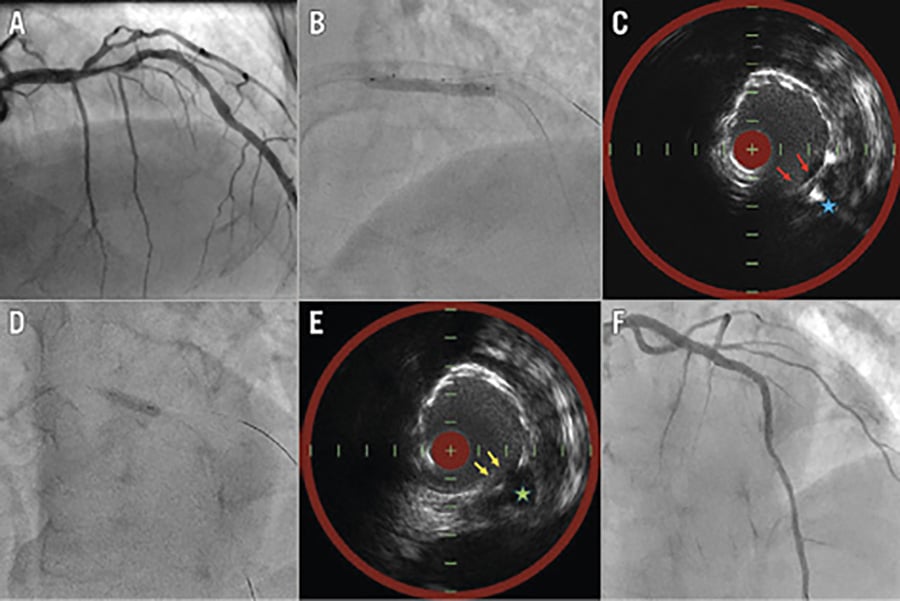
Figure 3. Contemporary JBT. A) Baseline angiogram showing long LAD disease from the proximal to mid-segment across a major diagonal. B) LAD stent deployment with an uninflated SB balloon. C) IVUS prior to POT showing the jailed SB wire (blue star) and minimal stent deformation (red arrows). D) POT performed with the jailed wire in situ. E) Final IVUS demonstrating the patent diagonal (green star) and good stent expansion without deformation (yellow arrows). F) Final angiogram confirming good results in both the LAD and diagonal arteries. IVUS: intravascular ultrasound; LAD: left anterior descending artery; JBT: jailed balloon technique; POT: proximal optimisation technique; SB: side branch
Modified jailed balloon technique
The modified JBT (M-JBT), described by Saito et al, is a variation of the JBT that has demonstrated high procedural success without SB occlusion.11 The technique involves positioning an SC balloon in the SB with its proximal end attached to the side of the MB stent (1-2 mm protrusion) and simultaneously inflating the balloon and the MB stent at similar pressures (usually 10-12 atm). This controlled inflation preserves SB patency by minimising plaque/carina shift, while reducing the risk of SB ostial dissection and avoiding deformation of the MB stent architecture. In a cohort of 254 bifurcation lesions (including 54 left main lesions), use of the M-JBT resulted in 100% procedural success with no SB occlusion. Bench testing demonstrated significantly less MB stent distortion compared with the conventional JBT.
Case example #3
A 63-year-old male presented with unstable angina. A coronary angiogram demonstrated severe stenosis of the mid-LAD, proximal to a medium calibre diagonal branch (Medina 1,0,0) (Figure 4A). After wiring and balloon predilation, a Cre8 EVO 3.0×40 mm DES (Alvimedica) was positioned in the proximal to mid-LAD, with a 2.0×12 mm SC balloon in the SB (Figure 4B). Both the stent and jailed balloon were simultaneously inflated to 12 atm (Figure 4C), then deflated before removal of the jailed SB balloon. OCT showed minor deformation of the MB stent at the level of the bifurcation (Figure 4D). POT and distal post-dilation were then performed. Final angiography and OCT (Figure 4E, Figure 4F) showed a widely patent SB, well-expanded LAD stent, and correction of stent deformation.
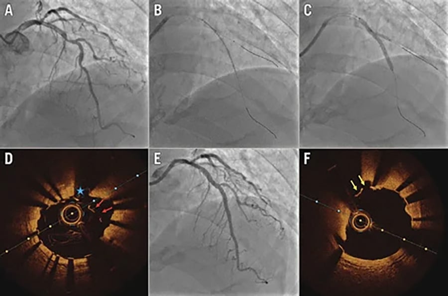
Figure 4. Modified JBT. A) Baseline angiogram showing severe mid-LAD disease involving a moderate-sized diagonal branch. B) LAD stent positioned with the SB balloon minimally protruding into the MB. C) Simultaneous inflation of the stent and the jailed SB balloon at 12 atm. D) OCT prior to POT showing the jailed SB wire (blue star) and minor stent deformation (red arrows). E) Final angiogram showing good results in both the LAD and diagonal. F) Final OCT demonstrating optimal stent expansion and correction of deformation (yellow arrows). LAD: left anterior descending artery; JBT: jailed balloon technique; MB: main branch; NC: non-compliant; OCT: optical coherence tomography; POT: proximal optimisation technique; SB: side branch
Active transfer of plaque
The active transfer of plaque (ATP) technique is a variation of the JBT that originated in Beijing Anzhen Hospital, China. In the ATP technique, the SB balloon is positioned with minimal protrusion (1-2 mm) into the MB and inflated until the balloon waist disappears (typically at 4-6 atm). This “fixes” the plaque in the MB when the stent balloon is inflated, reducing the risk of SB compromise due to plaque shift. The jailed SB balloon and stent balloons are removed and post-dilation/POT performed as usual. A multicentre observational study in China comparing ATP (n=560) with PS (n=576) showed that the rates of SB TIMI flow <3 (1.6% vs 7.5%; p<0.01), acute SB occlusion (1.3% vs 7.1%; p<0.01), and SB stent placement (1.8% vs 7.8%; p<0.01) were significantly lower in the ATP group.12 Schematic illustrations of JBTs using an inflated SB balloon are shown in Figure 5.
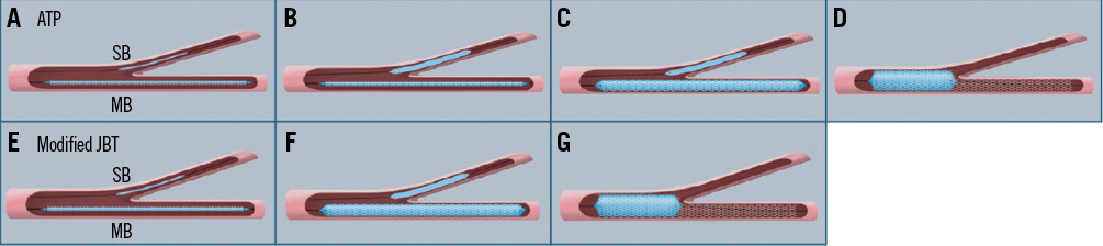
Figure 5. Inflated JBT techniques. Key steps of the ATP technique: minimal protrusion of the SB balloon (A), low pressure inflation of the SB balloon first at 4-6 atm (B), stent deployment with the SB balloon inflated (C), and final POT (D). Key steps of the M-JBT: minimal protrusion of the SB balloon (E), simultaneous inflation of the SB and stent balloons at 10-12 atm (F), and final POT (G). ATP: active transfer of plaque; JBT: jailed balloon technique; M-JBT: modified jailed balloon technique; MB: main branch; POT: proximal optimisation technique; SB: side branch
Case example #4
A 77-year-old male presented with an anterior STEMI. Coronary angiography demonstrated complex bifurcation disease (Medina 1,1,1) involving the proximal LAD and a major diagonal artery, with acute occlusion of the mid-LAD (Figure 6A). IVUS-guided PCI was performed with implantation of a 3.0×38 mm XIENCE DES (Abbott) in the mid-LAD, distal to the bifurcation. A 3.5×23 mm XIENCE DES was then positioned from the proximal to mid-LAD, with a 2.0×12 mm SC balloon placed in the diagonal branch. The SB balloon was inflated first at 6 atm, followed by LAD stent deployment (Figure 6B, Figure 6C). After post-dilation of the distal MB stent, the IVUS pullback demonstrated minor deformation of the proximal LAD stent at the bifurcation level (Figure 6D). POT was subsequently performed. Final angiography and IVUS (Figure 6E, Figure 6F) confirmed correction of stent deformation, good stent expansion, and preserved flow in both the LAD and the diagonal branch.
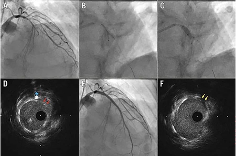
Figure 6. Active transfer of plaque. A) Baseline angiogram showing complex bifurcation disease of the proximal LAD and diagonal, with an occluded mid-LAD. B) SB balloon inflated at 6 atm. C) LAD stent deployed at nominal pressure while the SB balloon remains inflated. D) IVUS prior to POT showing the jailed SB wire (blue star) and minor stent deformation (red arrows). E) Final angiogram demonstrating good results in both vessels. F) Final IVUS demonstrating optimal stent expansion and correction of deformation (yellow arrows). IVUS: intravascular ultrasound; LAD: left anterior descending artery; POT: proximal optimisation technique; SB: side branch
Jailed microcatheter technique
Microcatheters can be used in active SB protection as an alternative to the jailed wire or various JBTs. The jailed Corsair (Asahi Intecc) technique, first described by Numasawa et al, was introduced to maintain SB patency while avoiding the risks associated with earlier JBT strategies, such as SB balloon rupture or dissection.13 Other coronary microcatheters may also be used for this technique. When performing the technique, it is essential that the microcatheter tip is positioned just beyond the proximal SB ostium without extending too distally, thereby reducing the risk of device entrapment. High-pressure inflation of the MB stent should also be avoided for the same reason. During removal, the microcatheter should be gently retracted with controlled rotation. Attention must also be paid to the guide catheter to avoid deep engagement and potential iatrogenic dissection of the proximal vessel. A schematic illustration of the jailed microcatheter technique is shown in Figure 7.

Figure 7. Jailed microcatheter technique: procedural steps. Key steps of the jailed microcatheter technique: the microcatheter is positioned with the distal tip a short distance into the SB (A), stent deployment (B), final POT (C). MB: main branch; POT: proximal optimisation technique; SB: side branch
Case example #5
An 81-year-old female underwent planned PCI for calcified LAD disease. Angiography demonstrated a long segment of disease involving an important diagonal branch (Medina 1,1,1) (Figure 8A). After wiring both branches, predilation with a 2.0×12 mm SC balloon facilitated IVUS for baseline assessment. IVUS revealed a short segment of concentric calcification (270° arc) in the mid-LAD at the level of the bifurcation (Figure 8B). The calcium distribution raised concern for potential SB compromise following stent implantation. After predilation with a 3.0 mm NC balloon, a FineCross microcatheter (Terumo) was advanced into the SB and jailed during deployment of a 2.75×46 mm Cre8 EVO DES in the LAD (Figure 8C). Following removal of the microcatheter and post-dilation of the distal LAD stent, IVUS demonstrated minor stent deformation attributable to the jailed microcatheter (Figure 8D). POT was subsequently performed. Final angiography and IVUS (Figure 8E, Figure 8F) confirmed good stent expansion, correction of the stent deformation, and preserved flow in both the LAD and diagonal branch.
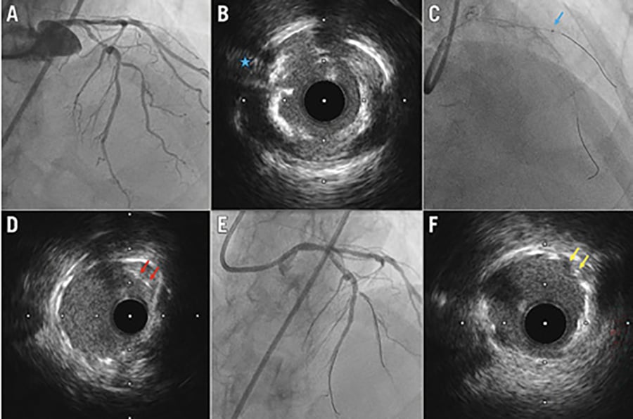
Figure 8. Jailed microcatheter technique. A) Baseline angiogram showing severe LAD disease involving an important diagonal artery. B) IVUS at the bifurcation showing concentric calcification (270°) adjacent to the SB ostium (blue star). C) LAD stent positioned with a FineCross microcatheter jailed in the SB (blue arrow). D) IVUS prior to POT showing minor stent deformation caused by the microcatheter (red arrows). E) Final angiogram showing good results in both the LAD and diagonal. F) Final IVUS demonstrating optimal stent expansion and correction of stent deformation (yellow arrows showing the corresponding position). IVUS: intravascular ultrasound; LAD: left anterior descending artery; POT: proximal optimisation technique; SB: side branch
Technical variations and considerations
Sizing of the jailed balloon
In the JBT, the size of the SB balloon should be smaller in diameter than the size of the MB stent. Typically, the MB stent is sized to the distal landing zone, and the SB balloon should be approximately half the diameter of the stent (i.e., 3.0 mm MB stent and 1.5 mm jailed balloon).11 However, SB balloon sizing also depends on the SB calibre, and the authors recommend a 0.5-0.8:1 ratio of the balloon to SB diameter based on angiographic estimate or IVUS/OCT measurements. The two main reasons for the relatively conservative SB balloon sizing are as follows: (1) the primary goal for active SB protection is to maintain patency of the SB, rather than achieving minimal residual stenosis at the SB ostium; and (2) it minimises the risk of SB dissection in inflated versions of the JBT (M-JBT at super-nominal and ATP at low pressures) or when SB balloon inflation rescue is required.
Jailed drug-coated balloon
The jailed drug-coated balloon (DCB) technique is a novel adaptation of the M-JBT for true bifurcation lesions at high risk of SB compromise.14 After lesion preparation, an appropriately sized DCB, instead of an SC balloon, is positioned in the SB with its proximal end within the MB stent. The DCB is inflated first, followed by the stent, both to nominal pressures. The MB stent balloon is then deflated first, while the DCB remains inflated for 60 seconds to deliver antiproliferative therapy, minimising neointimal hyperplasia and preserving SB patency while reducing restenosis risk without permanent SB scaffolding. After removal of both balloons, POT and post-dilation are then performed.
Timing and tips to remove jailed equipment
Even after successful stent implantation with active SB protection, SB closure can occur during post-dilation or POT. A variation of the JBT that some operators employ is post-dilating the distal MB stent and across the bifurcation prior to removing the jailed equipment. The authors recommend this in cases of narrow bifurcation angles (<70°) or if the SB flow is already compromised after stent deployment, requiring rescue inflation. It is important to remove the jailed balloon before POT is performed to avoid trapping the equipment. In the collective experience of the authors, no jailed equipment (balloons/microcatheters) has been entrapped, whether removed before or after post-dilation across the bifurcation.
Jailing the SB wire during POT should be decided on a case-by-case basis. Keeping the jailed wire in situ during POT to serve as a marker for SB rewiring may be useful in situations including (1) a compromised SB prior to POT, (2) significant soft plaque burden in the proximal MB near the bifurcation which may shift during POT, and (3) significant proximal MB dissections with/without haematoma during lesion preparation. In the presence of severe calcification, removal of the jailed wire prior to POT is recommended if there is minimal risk of SB occlusion, to avoid entrapment in the calcium. If a polymer-jacketed wire is used in the SB initially, it is important to either exchange it with a workhorse wire using a microcatheter (which can also be used as a jailed microcatheter) or remove it prior to POT. Resistance while removing a jailed polymer-jacketed wire runs the risk of wire damage and shearing of the polymer.15
Like in the removal of jailed guidewires, there may be resistance in removing the jailed equipment which often cause deep engagement of the guiding catheter. This can increase the risk of distal wire perforations, guide-induced dissections, and longitudinal stent deformation, depending on the proximity of the stent edge to the coronary ostium. This can be mitigated by one or more of these simple techniques: (1) careful withdrawal of the guiding catheter into the aortic root before removal of the jailed equipment, (2) placement of a floating wire in the aortic root, or (3) the use of a balloon anchor in the distal MB stent.
Side branch rescue
In PS, SB occlusion most often occurs after MB stent deployment, though mechanisms vary by stage and protection strategy. Early occlusion, before post-dilation/POT, may result from balloon-induced injury with inflated protection (M-JBT/ATP) or from plaque/carina shift, dissection, or embolisation when inflation is not used (C-JBT). In these cases, inflation of the jailed balloon at the SB ostium can relieve compression, restore flow, and act as a temporary scaffold. If flow is re-established, the operator may proceed with POT and reassess the SB.
Occlusion after POT is usually due to plaque shift or distal balloon placement, particularly with wide bifurcation angles (>70°) or heavy plaque burden at the SB ostium on IVUS/OCT. Rewiring the SB before POT should be considered in high-risk cases. When rewiring is needed, dual-lumen microcatheters or imaging can confirm luminal passage, while abluminal wiring remains a risk when “looping” a wire through the stent. Rewiring through a distal stent cell can be reliably confirmed using intravascular imaging, most notably OCT with three-dimensional bifurcation reconstruction. Alternatively, a proximally positioned POT (away from the bifurcation) may help to mitigate abluminal wiring while minimising the risk of SB occlusion from plaque shift. If rewiring is unsuccessful, POT can be repeated before further attempts. Rescue options include external KBI with a small balloon advanced over the SB wire or use of torqueable microcatheters to access the SB beneath the MB stent, which will also aid in the removal of the jailed wire.161718 A distal balloon anchor can increase support for equipment delivery and help correct stent deformation. The success of this technique depends on vessel angulation, plaque morphology behind the stent, guide support, and the length of the proximal MB stent which the equipment needs to travel under.
If the SB is rewired successfully, KBI and final POT should be performed in a routine manner. Alternatively, recent randomised studies have demonstrated that DCBs can either be applied directly to the stenotic SB ostium after opening the stent cell or used after KBI/POT.1920 A bailout two-stent strategy may be required if there is type C dissection or reduced TIMI flow, using the T and small protrusion (TAP), reverse crush, or culotte techniques, depending on anatomical considerations and operator preference.
Case example #6
A 78-year-old female underwent coronary angiography for acute coronary syndrome. Angiography demonstrated severe mid-LAD stenosis across a major diagonal artery bifurcating into two branches (Figure 9A). Baseline OCT assessment of the LAD revealed heavy lipid plaque burden at the bifurcation adjacent to the SB ostium with a branch point-carina tip length of 0.6 mm (Figure 9B, Figure 9C). Following predilation, a 3.0×24 mm SYNERGY DES was deployed in the LAD with an uninflated 1.5×15 mm SC balloon jailed in the upper diagonal branch (Figure 9D). The jailed balloon was left in situ during post-dilation with a 3.0 mm NC balloon. SB occlusion occurred after post-dilation, so an external KBI was performed, restoring TIMI 3 flow (Figure 9E). Following POT with a 4.0×6 mm NC balloon, SB flow was lost again (Figure 9F). The 1.5 mm balloon was readvanced over the jailed SB wire to perform rescue inflation and external KBI again to restore flow (Figure 9G). Final POT was performed more proximally, with good final angiographic and OCT results (Figure 9H–Figure 9J).
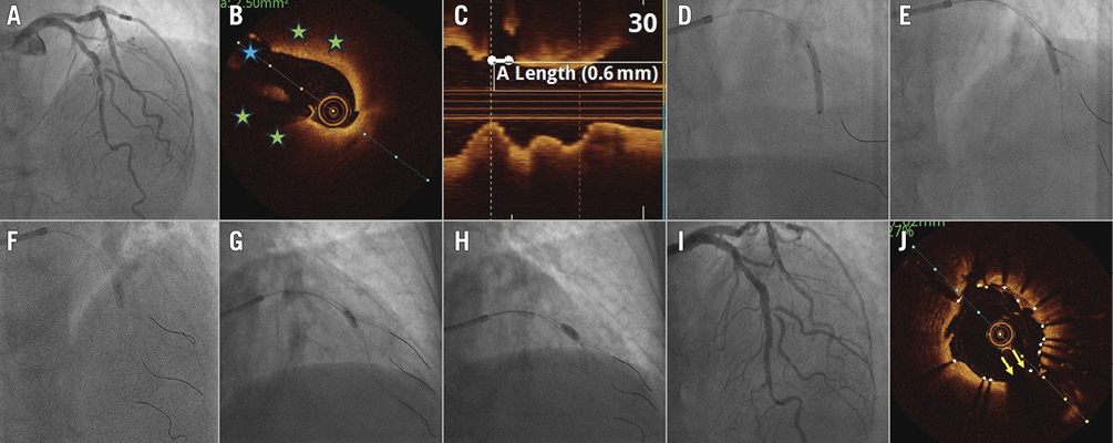
Figure 9. SB rescue with external KBI. Baseline angiogram showing severe mid-LAD stenosis across a major diagonal bifurcating into two sub-branches. B-C) Baseline OCT showing heavy lipid plaque burden (green stars) adjacent to the SB ostium (blue star) with a short branching point-to-carina tip length of 0.6 mm. D) LAD stent deployment with an uninflated 1.5 mm jailed SB balloon. E) External KBI with the jailed 1.5 mm balloon and a 3.0 mm NC balloon. F) POT balloon inflation. G) Readvancement of the 1.5 mm balloon underneath the proximal MB stent for repeat external KBI. H) POT performed in a more proximal position. I) Final angiogram showing good results in the LAD and both diagonal branches. J) Final OCT demonstrating good stent expansion without deformation at the bifurcation (yellow arrows). KBI: kissing balloon inflation; LAD: left anterior descending artery; MB: main branch; OCT: optical coherence tomography; POT: proximal optimisation technique; SB: side branch
Discussion
In most cases, active SB protection serves as a practical extension of the PS strategy in bifurcation lesions. Routine predilation of a diseased SB ostium before performing an active protection technique should generally be avoided, as it may provoke dissections that necessitate escalation to more complex bifurcation strategies. Exceptions include the presence of baseline slow flow in the SB or scenarios involving a jailed drug-coated balloon, where lesion preparation is required to facilitate drug delivery. The techniques outlined in this review are summarised in Table 1; these represent commonly employed methods in contemporary practice, though they do not encompass the full spectrum of described active protection strategies. These approaches generally exhibit a more favourable learning curve and fewer procedural challenges compared with dedicated two-stent bifurcation techniques. A meta-analysis that included 1,174 patients concluded that active SB protection significantly reduced SB compromise but did not affect rates of periprocedural myocardial infarction or long-term prognosis.21 When active SB protection techniques are utilised in the correct anatomical and clinical settings, they may simplify or shorten the procedure by reducing the need to routinely rewire because of SB compromise. Importantly, multiple studies have shown that SBs that are compromised after main vessel stenting are frequently functionally non-significant by fractional flow reserve despite severe angiographic narrowing, reinforcing the primary objective of active SB protection: the preservation of SB flow.2223
Although current guidelines recommend intravascular imaging primarily for complex bifurcation lesions, the authors advocate its routine use in all bifurcation interventions.2425 Intravascular imaging enables a more precise assessment of SB occlusion risk beyond angiographic evaluation by characterising factors such as plaque burden at the bifurcation, degree of calcification, and carina tip length. Beyond facilitating the accurate sizing of stents and balloons, intravascular imaging is critical for detecting and correcting unintentional stent deformation (USD). In the OCTOBER trial, USD was observed in 9.3% of bifurcation lesions and 18.5% of left main interventions.26 USD, commonly resulting from abluminal wiring or guide catheter-stent interactions, has been linked to a 23.3% rate of major adverse cardiovascular events at two years if left uncorrected.
Two primary concerns among operators new to active SB protection techniques are the risks of stent deformation and equipment entrapment. In our case examples, intravascular imaging was routinely performed following stent deployment to quantify the stent deformation, which was subsequently corrected with POT. The consistent use of intravascular imaging facilitates accurate POT with appropriately sized NC balloons to address any deformation. While an isolated case of jailed balloon entrapment has been reported by Numasawa et al, attributed in part to repeated stent balloon inflations, ex vivo data from Skowroåski et al demonstrate that multiple inflations can cause greater stent expansion, potentially increasing entrapment risk.2728 However, multiple observational studies of the jailed balloon technique have reported no device entrapment, findings that are supported by our own experience.293031
To our knowledge, no head-to-head studies have compared the various active SB protection techniques. Nonetheless, the overarching objective of preserving SB patency during PS remains consistent, particularly in complex anatomies. Selection of a specific technique is typically influenced by operator experience, equipment availability, and guide catheter size. Operators early in their learning curve may evaluate multiple active SB protection techniques to identify the approach that aligns best with their procedural style and workflow.
Table 1. Active SB protection techniques in bifurcation PCI.
| Technique | Key procedural steps | Advantages | Disadvantages |
|---|---|---|---|
| Conventional JBT | Uninflated SB balloon extending beyond the proximal stent edge Rescue inflation if TIMI ↓ | Familiar technique Theoretically lowest risk of device entrapment | Long length of proximal MB stent deformation |
| Contemporary JBT | Uninflated SB balloon with minimal protrusion into the MB during stent deployment Rescue inflation if TIMI ↓ | Familiar technique Minimal MB stent deformation | Rescue inflation may still deform the MB stent |
| Modified JBT | Simultaneous inflation of the stent/SB balloons at 10-12 atm, with minimal protrusion into the MB | Strong clinical and bench-testing data Low risk of SB occlusion after stent deployment | Requires precise positioning and simultaneous inflation |
| Active transfer of plaque | SB balloon inflated first at 4-6 atm, with minimal protrusion into the MB, followed by stent deployment | Strong clinical data Low risk of SB occlusion after stent deployment | Limited global adoption outside China and Hong Kong |
| Jailed microcatheter technique | Microcatheter extending slightly into the SB during MB stent deployment Careful removal with gentle rotation | Avoids balloon rupture/dissection | Requires ≥7 Fr guide |
| JBT: jailed balloon technique; MB: main branch; PCI: percutaneous coronary intervention; SB: side branch; TIMI: Thrombolysis in Myocardial Infarction | |||
Conclusions
Active SB protection offers a practical and adaptable approach to managing coronary bifurcation lesions within a PS strategy. By reducing the risk of SB occlusion and minimising the need for complex bailout techniques, especially when supported by intravascular imaging, this approach can enhance procedural safety and efficiency. Continued operator training and prospective evaluation will help define its optimal role in contemporary bifurcation PCI.
Conflict of interest statement
B. Wong has received honoraria from Bio-Excel. E. Wu has received honoraria from Teleflex and Kaneka; he has received proctoring fees from Kaneka and Boston Scientific; and he is Director of APCTO Club, a registered charity in Hong Kong, which receives educational grants from Abiomed, Asahi Intecc, and OrbusNeich. S. Harding has received consulting fees/honoraria from Abbott, Boston Scientific, Teleflex, and Bio-Excel; and he has individual stock options in Seigla Medical. The other authors have no conflicts of interest to declare regarding the content herein.